Where Does the Brake Booster Vacuum Hose Go? Connection Guide
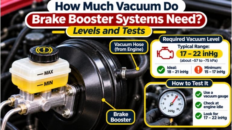
On most gasoline-powered vehicles with a conventional vacuum brake booster, the brake booster vacuum hose runs from a large vacuum port on the engine’s intake manifold to the one-way check valve at the brake booster. On vehicles that use a mechanical or electric vacuum pump, the hose instead connects the booster to that pump or to an approved vacuum supply line.
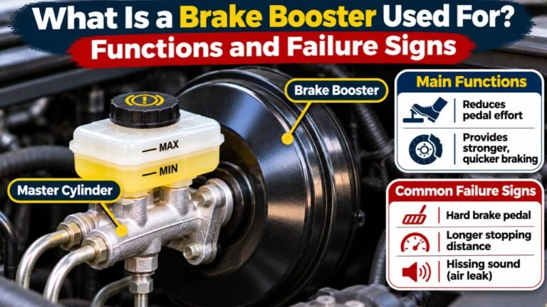
The booster is usually the large round housing behind the brake master cylinder, near the firewall. Its vacuum hose is generally thicker and more rigid than many small engine-control vacuum lines. It may include a molded elbow, plastic tubing, an inline check valve, or quick-connect fittings, depending on the vehicle.
Finding the correct connection matters because the booster uses vacuum to reduce the effort required to press the brake pedal. A disconnected, split, or incorrectly routed hose may leave the pedal unusually hard and make stopping difficult. This guide shows where each end belongs, how to trace the hose safely, how different engines supply vacuum, what the check valve does, and how to recognize a faulty connection.
Where Does the Brake Booster Vacuum Hose Go on Most Cars?
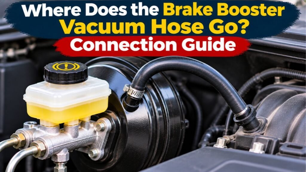
The usual routing is straightforward: intake manifold vacuum source → brake booster vacuum hose → one-way check valve → brake booster. The check valve may be built into the elbow at the booster, placed inside the hose, or located somewhere along the line. The exact arrangement varies by manufacturer.
The intake manifold is the part of the air-intake system that distributes air to the engine’s cylinders. On a typical naturally aspirated gasoline engine, the brake booster takes vacuum from a manifold port downstream of the throttle plate. It does not normally use a random small port on the air-filter box or a hose that carries brake fluid.
The 2002 Jeep Wrangler brake booster service description identifies one hose end at the intake manifold fitting and the other at the booster’s check valve. That describes its specific system, not a universal mounting location for every engine.
The engine-side connection might sit on top of the intake plenum, behind the engine, or near the throttle body. Identify it using the vehicle’s vacuum routing diagram rather than assuming that two nearby-looking nipples serve the same purpose.
Which End of the Hose Connects to the Brake Booster?
The Booster End: Check Valve or Vacuum Elbow
Look for a large, round or oval brake booster mounted to the firewall, typically with the master cylinder bolted to its front. The hose connects to a valve or fitting inserted into a rubber grommet in the booster housing. Some vehicles use a straight connector; others use a plastic right-angle elbow.
The grommet seals the connection where the valve enters the booster. If it is cracked, hardened, or loose, the system can leak even when the hose itself looks healthy. Do not mistake the brake-fluid reservoir above the master cylinder for a vacuum connection.
The Engine End: Dedicated Manifold Port or Pump Inlet
Follow the hose away from the booster. On many gasoline engines it ends at a relatively large nipple or threaded fitting on the intake manifold. On a vacuum-pump-equipped vehicle, it ends at the pump’s vacuum-side connection, sometimes through molded piping, tees, sensors, or a reservoir.
This is a suction connection, not a fuel line, coolant hose, exhaust-gas line, or positive crankcase ventilation (PCV) connection. Never connect it based only on hose diameter. A wrong port may deliver no usable vacuum or introduce an engine air leak.
How to Trace the Brake Booster Vacuum Hose Under the Hood
The following checks help identify the correct route without opening the hydraulic brake system. Work with the ignition off and the engine cool unless an approved diagnostic procedure specifically requires otherwise.
Step 01: Find the Master Cylinder and Booster
Open the hood and locate the brake-fluid reservoir. Beneath it is usually the master cylinder, which attaches to the larger booster housing toward the firewall. Locate the vacuum fitting in the housing, often near its upper edge.
If there is no round housing, check the service information before searching for a hose. The vehicle may use a hydraulic or integrated electric brake-assist system instead.
Step 02: Identify the Check Valve and Hose Connection
Look for the plastic elbow, check valve, or sealed connector on the booster. Follow the hose attached to it and inspect the immediate fitting for broken tabs or a loose rubber seal. Some models have a check valve built into the hose rather than at the housing, so the pieces may not look like separate parts.
Avoid pulling on the valve just to confirm that you found it. A brittle elbow or hardened grommet may crack during unnecessary removal.
Step 03: Follow the Hose Toward Its Vacuum Source
Trace the line visually and by hand while keeping clear of sharp edges. It may run along the firewall, across the engine, or behind intake ducting. Follow any hard plastic tube connected to the flexible rubber sections; do not assume the hose ends where the rubber stops.
If the line disappears under a cover, consult the routing diagram before removing components. Photograph its existing position so clamps and clips can be restored correctly.
Step 04: Confirm the Correct Engine-Side Fitting
At the engine end, identify whether the hose joins the intake manifold or a dedicated vacuum pump. Check for molded markings, original clips, and the parts diagram for the engine fitted to that vehicle. On a turbocharged engine, routing may include extra valves or control components to keep boost pressure out of the booster circuit.
Do not substitute an unused manifold nipple or tee into another vacuum hose. Matching the intended source and connection size is essential for reliable brake assistance.
Step 05: Check for Damage Along the Entire Route
Inspect rubber portions for splits, hardened ends, swelling, and collapse. Check molded plastic sections for cracks, worn spots, and broken retaining clips. Pay attention to bends, the point where the line passes behind the engine, and areas exposed to heat.
A hose can appear connected while leaking around a loose end or deteriorated grommet. If the line was found disconnected, inspect why it came off instead of simply pushing it back onto a damaged fitting.
Step 06: Verify the Connection Before Driving
Reconnect only with the correct vehicle-specific parts and routing. Seat each fitting fully, install the original-style retainers, and make sure the check valve has the correct orientation. The hose should not pull against the connector, contact the exhaust, or rub on moving engine parts.
Afterward, perform the specified stationary brake-assist checks. If the pedal remains hard, the engine runs poorly, or a leak is suspected, do not road-test the vehicle; arrange a proper diagnosis.
Does the Vacuum Hose Connect Differently on Diesel, Turbo, and Hybrid Vehicles?
| Vehicle System | Typical Vacuum Source | Routing Detail |
| Naturally aspirated gasoline engine | Intake manifold | Hose usually goes to a dedicated manifold vacuum fitting |
| Turbocharged gasoline engine | Manifold and/or supplemental pump | May use additional check valves or controlled vacuum plumbing |
| Diesel engine with vacuum assist | Mechanical or electric pump | Often connects to a pump because intake vacuum is insufficient |
| Hybrid or stop-start vehicle with vacuum assist | Electric or supplemental pump | May include sensors, a reservoir, or electronically controlled supply |
| Hydraulic or integrated electric brake assist | No conventional booster vacuum supply | May have no booster vacuum hose at all |
The HELLA technical guide to electric vacuum pumps explains that an electric pump can supply a brake booster when the engine intake does not provide adequate vacuum. Its description also shows why pump-equipped vehicles may have more plumbing than a simple manifold-to-booster hose.
An engine’s fuel type alone cannot tell you the exact hose route. Some diesels have vacuum pumps driven by the engine, and modern gasoline engines can use supplemental pumps. Identify the brake-assist hardware installed on that particular vehicle, not just the badge on the trunk.
Why the Brake Booster Vacuum Check Valve Is Important
The one-way check valve helps the booster hold a limited reserve of vacuum when engine vacuum drops or the engine stops. This can preserve some brake assistance for a small number of pedal applications; it is not a substitute for a working vacuum source.
The valve must allow the system’s vacuum source to evacuate air from the booster while resisting reverse airflow that would quickly eliminate stored assistance. A valve installed backward can block the intended vacuum path. Some assemblies use arrows or molded labels, but these markings must be interpreted according to the part instructions.
A valve may be in the booster’s rubber grommet, inside its elbow, or integrated into the hose. If a manufacturer specifies replacing the hose and check valve together, do not cut the assembly apart and install a generic valve. If orientation is uncertain, consult the model-specific diagram before starting the engine.
What Happens if the Booster Vacuum Hose Is Disconnected or Leaking?
The most noticeable symptom is often a hard brake pedal that requires far more effort than usual. The mechanical connection between the pedal and master cylinder may still work on a conventional system, but the loss of power assistance can make stopping difficult and increase stopping distance.
On an engine that draws vacuum from its intake manifold, a disconnected hose also acts as a substantial air leak. The engine may idle roughly, run lean, or stall, depending on its design and operating conditions. A hissing sound near the firewall or manifold can indicate air entering through a damaged hose, grommet, or valve.
An occasional firm pedal after several engine-off applications is not by itself proof of a leak; those applications can consume stored vacuum. A sudden change while driving, especially with poor braking response, requires immediate attention. Stop in a safe place and arrange towing or qualified inspection rather than continuing to drive.
How to Check the Brake Booster Vacuum Hose and Assist Function
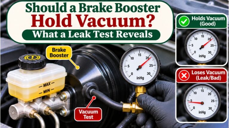
Start with an engine-off visual inspection of the full hose, its clips, and both endpoints. Check that unused intake ports are properly sealed, the hose is not collapsed, and the valve and booster grommet have no obvious damage. An external vacuum gauge or hand pump can help a technician determine whether vacuum reaches the booster and whether the valve retains it.
A basic stationary check on some conventional vacuum-boosted vehicles is to press the brake pedal several times with the engine off, hold steady pedal pressure, and then start the engine. A modest downward movement of the pedal suggests that assistance has become available. No movement calls for further diagnosis; it does not automatically prove the booster itself has failed.
The 2004 Ford Focus brake booster diagnostic procedure begins with hose, connection, and check-valve inspections before evaluating booster response and vacuum supply. Follow the corresponding instructions for your own vehicle rather than applying Ford’s tests or specifications universally.
Do not run the engine with a hose deliberately disconnected to guess which port pulls vacuum. Unexpected engine movement, a large air leak, and loss of brake assistance make that a poor substitute for proper service equipment.
Can You Replace or Reconnect the Hose Without Bleeding Brakes?
Replacing only the external vacuum hose normally does not require bleeding the hydraulic brakes, provided no brake-fluid line or master-cylinder hydraulic connection was opened. The vacuum circuit and brake-fluid circuit perform different jobs, even though they work together during a brake application.
Use a hose or molded assembly approved for brake-booster vacuum service. General-purpose rubber tubing may soften, collapse under suction, deteriorate in the engine compartment, or fit the check valve poorly. A molded factory assembly is often necessary where the line crosses tight bends or includes integrated valves.
Match the original connector size, check-valve orientation, and retaining method. Do not install a smaller hose by stretching it or seal a loose connection with tape. If the master cylinder or brake lines were disconnected during other work, bleeding requirements are determined by that hydraulic service, not by the vacuum hose alone.
FAQs About Where Does the Brake Booster Vacuum Hose Go
Does the Brake Booster Hose Connect to the Intake Manifold or Throttle Body?
On many gasoline engines it connects to a dedicated intake-manifold vacuum port, usually downstream of the throttle plate. The physical port may be close to the throttle body, but proximity alone does not make another fitting correct.
Is the Brake Booster Vacuum Hose Connected to the Master Cylinder?
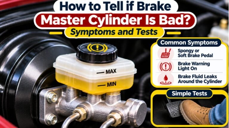
No. The hose connects to the booster or its check valve, not to the master cylinder’s brake-fluid ports. The master cylinder is mounted immediately in front of the booster, which can make the two easy to confuse.
Can I Use Any Vacuum Hose for the Brake Booster?
No. Use a vacuum-rated hose or a vehicle-specific assembly with the correct size, fittings, durability, and routing. Some systems contain an integral one-way valve or molded plastic sections that a generic hose cannot replace safely.
Which Way Should the Brake Booster Check Valve Face?
It must face the direction required by the original part and vehicle service diagram so vacuum can be maintained inside the booster. Do not rely on the appearance of the elbow or guess from a generic arrow without checking what the marking means.
Can a Disconnected Brake Booster Hose Cause Rough Idle?
Yes. If the hose draws from the intake manifold, a disconnected or split line can admit unmetered air and disturb engine operation. It may also reduce brake assistance, making the problem urgent even if the engine still runs.
Does a Hydraulic Brake Booster Have a Vacuum Hose?
Generally, no. Hydro-boost systems use hydraulic assistance, often associated with a power-steering hydraulic circuit, instead of a conventional vacuum booster. Some modern integrated electric brake systems also have no external vacuum hose.
Getting the Brake Booster Vacuum Hose Connected to the Right Source
The answer to “where does the brake booster vacuum hose go” depends on the installed brake-assist design. On many gasoline vehicles, it joins a dedicated intake-manifold vacuum fitting to the check valve at the booster. On pump-equipped systems, the line follows the manufacturer’s path to a mechanical or electric vacuum source instead.
The safest approach is to identify both ends, trace the complete factory routing, and inspect the hose, check valve, and grommet rather than connecting it to whichever port appears to fit. A secure connection and correct valve orientation are essential for dependable assistance.
If the hose has come loose or the pedal feels harder than normal, keep the vehicle off the road until the cause is corrected and the brake system passes the appropriate stationary and professional checks.