Which Line on Master Cylinder Is for Rear Brakes? Port Guide
There is no universal master cylinder port that always feeds the rear brakes. On a front/rear split system, one hydraulic circuit serves the rear axle, but its outlet position varies by vehicle. On a diagonal split system, both master cylinder circuits serve a rear wheel.
The distinction matters if you’re replacing a master cylinder, reconnecting brake pipes, or tracing a rear-brake problem. The outlet closest to the firewall may look like the obvious rear connection, but its physical location does not establish which wheels it operates. On many vehicles with anti-lock brakes, the master cylinder’s two lines first enter an ABS hydraulic control unit.
Mixing up the circuits can create serious braking problems, and disconnecting a line just to see where fluid comes out introduces air into a safety-critical system. The reliable approach is to identify the hydraulic layout and follow the correct line-routing diagram. I’ll explain the main circuit designs, how to locate the rear-brake supply without opening a fitting, how combination valves and ABS affect the route, and which clues should never be used alone.
Which Line on Master Cylinder Is for Rear Brakes?
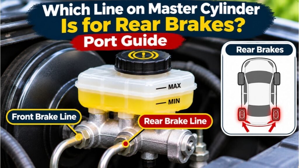
The answer depends on how the manufacturer divided the hydraulic system. A conventional tandem master cylinder contains two pressure chambers. Each chamber supplies an independent circuit, but two master cylinder outlets do not necessarily mean one front outlet and one rear outlet.
Here is the practical difference:
| Brake Circuit Layout | Where the Master Cylinder Lines Go | Which One Serves Rear Brakes? |
| Front/rear split | One circuit serves the front axle; the other serves the rear axle | One designated outlet supplies the rear circuit |
| Diagonal split | Each circuit serves one front wheel and the opposite rear wheel | Both master cylinder circuits include a rear wheel |
| ABS-equipped system | Master cylinder outlets often connect to an ABS hydraulic unit | Identify rear-wheel outlets downstream of that unit using the vehicle diagram |
| Custom or older conversion | Routing depends on the installed master cylinder and valves | Follow the specific component’s installation instructions |
A generic drawing may show a valid connection for another vehicle. Confirm the make, model, year, and brake configuration before identifying an outlet.
Front/Rear Split vs. Diagonal Split Brake Lines
Front/Rear Split: One Circuit for Each Axle
In a front/rear split arrangement, one master cylinder pressure chamber connects to the front brakes and the other to the rear brakes. A leak in one circuit may leave the other functional, but braking ability is severely reduced.
Some older vehicles, trucks, and modified applications use this layout. The rear line may pass through a combination valve before branching toward both rear wheels.
Still, the rear reservoir chamber does not necessarily supply the rear axle. Internal plumbing determines the destination.
Diagonal Split: Each Circuit Includes a Rear Wheel
A diagonal split divides braking between opposite corners: commonly the left-front and right-rear wheel on one circuit, and the right-front and left-rear wheel on the other. The exact designation of the primary and secondary circuits varies by vehicle.
This arrangement can preserve one front and one rear wheel if one circuit fails. Thus, both circuits contribute to rear braking.
Two pipes entering an ABS unit may both run forward while still carrying diagonal circuits.
Is the Rear Brake Port Closest to the Firewall or the Front?
You may see advice that the front, nose-end outlet feeds the rear brakes, or that the port nearest the booster does. Neither rule applies to every master cylinder. Manufacturers use different port arrangements, and replacement cylinders or aftermarket conversions may differ from original equipment.
A useful example comes from Master Power Brakes’ 1964–1966 Mustang conversion kit instructions. Its brake-line routing diagram labels the nose-end outlet for the rear brakes and other outlets for the front brakes. That drawing identifies that specific kit’s plumbing, not all Mustangs and certainly not every modern car.
Use terms like “nose-end outlet” and “booster-end outlet” for position alone. Primary and secondary designate chambers or circuits, not universal axle assignments.
Reservoir size is unreliable too. On some older disc/drum systems, a larger section supplied front calipers as pads wore, but modern designs need not follow that pattern.
How ABS Changes the Rear Brake Line Routing
An ABS-equipped vehicle commonly sends hydraulic pressure from the master cylinder to the ABS hydraulic control unit, which then distributes pressure to individual wheel brakes. Depending on the design, the unit may also handle electronic brake-force distribution. The master cylinder lines are therefore inlet lines to the ABS unit, not necessarily direct front- or rear-axle pipes.
For a documented example, the 2000 Dodge Intrepid master cylinder service description specifies that one circuit supplies the right-front and left-rear brakes while the other supplies the left-front and right-rear brakes. On ABS versions, the master cylinder tubes connect to the integrated control unit rather than going straight to the wheels.
Tracing a tube to the ABS block is not enough. You must identify its internal circuit and outlet.
ABS units crowd several pipes together. Some have port markings; others require diagrams. Never interchange ports experimentally. Powered brake systems may also need specific depressurization and bleeding procedures.
How to Identify the Rear Brake Line Without Opening the System
The safest identification method relies on information and inspection, not fluid release. These steps are useful when you’re checking existing connections or preparing to replace a correctly specified component.
Step 01: Identify the Vehicle’s Exact Brake Configuration
Record the model year, make, model, engine or trim where relevant, and whether the car has ABS. Check whether it has rear discs or drums and whether major brake components have been replaced with aftermarket parts.
Similar-looking vehicles can have different line layouts. A modified classic may not match its original service diagram.
Step 02: Find the Hydraulic Brake Line Diagram
Use the factory service manual or a reputable repair information source for that exact configuration. Search within the braking section for hydraulic lines, master cylinder connections, ABS hydraulic control unit, or brake pipe routing.
Read the diagram’s legend carefully. Labels such as LF, RF, LR, and RR usually identify left front, right front, left rear, and right rear, but confirm the manual’s conventions. Compare the drawn connection locations with the actual fittings on the vehicle before concluding which line serves the rear brakes.
Step 03: Locate the Master Cylinder and Count the Outlets
With the vehicle parked, ignition off, and the brake system in its specified safe service state, locate the master cylinder on the booster or firewall. Identify the hard metal brake pipes and distinguish them from reservoir hoses, electrical connectors, and nearby ABS piping.
Count and photograph the outlet fittings without loosening them. A two-outlet cylinder may feed a front/rear circuit, diagonal circuits, or an ABS unit. More visible connections do not automatically mean a separate circuit for every wheel.
Step 04: Trace the Pipes to Their Next Connection
Use a flashlight to follow each hard line from the master cylinder to a combination valve, junction, or ABS block. Note clamps and bends that make the pipe identifiable. If tubes cross, follow each individually.
You may be able to confirm that a particular line goes directly to a rear-axle distribution point on an older system. On an ABS-equipped car, tracing typically stops at the hydraulic unit; use the diagram to follow the corresponding circuit through that unit. Never tug on a brake pipe or bend it aside to improve the view.
Step 05: Compare Port Labels and Valve Connections
Check for manufacturer markings on the cylinder, a distribution block, or a proportioning valve. A custom valve may use labels such as FRONT, REAR, IN, and OUT, but their meanings depend on that part’s installation instructions.
Match these markings against the exact part number. A word stamped near a valve outlet is not enough if the assembly has been installed backward or modified. If markings conflict with the service manual or existing pipe routing, stop and resolve the discrepancy before any reassembly.
Step 06: Document the Confirmed Rear-Brake Path
Once the diagram and physical routing agree, label the lines with removable tags and take photographs that show where each tube begins and ends. Record which master cylinder port feeds the rear axle or which two circuits contain the rear wheels.
Keep these records to prevent misconnection during repair. If uncertain, have a brake technician verify the route.
What Proportioning and Combination Valves Tell You
On a conventional front/rear split system, the rear circuit may pass through a proportioning valve. This valve helps manage rear hydraulic pressure under harder braking so the rear wheels are less likely to lock before the fronts. A combination valve can also incorporate distribution and warning functions, depending on its design.
For example, the Wilwood combination proportioning valve product documentation identifies an isolated rear circuit with one inlet and one outlet, while the front circuit has a separate inlet and two available outlets. Those labels help identify the rear route on that valve and compatible systems; they are not universal directions for every factory master cylinder.
Many newer ABS-equipped cars use electronic brake-force distribution instead of a separate, easily recognizable rear proportioning valve. Therefore, not finding a valve in the engine bay does not prove that both master cylinder pipes serve the front wheels.
Master Cylinder Line Identification Mistakes That Cause Problems
Assuming the Rear Port Means Rear Wheels
The term rear port usually describes the outlet’s position relative to the mounting flange. It doesn’t confirm that the line supplies the rear axle. A part description may also use “rear circuit” to describe a specific internal chamber, creating further confusion.
Use the manufacturer’s hydraulic diagram, not the position-based nickname, to determine wheel assignments.
Using Brake Pipe Diameter or Fitting Size as Proof
Brake pipes can differ in diameter or flare nut size, and a replacement master cylinder may have different-sized threads that discourage incorrect assembly. However, neither feature reliably identifies the rear brakes across makes and models.
Never force a fitting that seems to belong in a different port. A thread may start even when the tube’s flare or seat is incompatible, leaving a connection that cannot seal safely.
Swapping Lines to Solve Poor Rear Braking
Weak rear braking is not proof that two master cylinder lines were reversed. A soft pedal, corrosion, trapped air, restricted hoses, seized rear calipers, improperly adjusted drum brakes, ABS faults, and leaks can all affect rear braking.
If the system was recently repaired, check the recorded routing against the correct service diagram. Do not swap the fittings as a trial-and-error test. Opening the system introduces air, and the wrong connections can defeat the intended hydraulic circuit design.
What to Check When Rear Brakes Have Little or No Pressure
If the question comes from a rear-brake problem rather than a plumbing job, first determine whether the vehicle has a dedicated rear circuit or diagonal circuits. A complaint affecting both rear wheels may involve different causes depending on the layout.
On a front/rear split vehicle, inspect for leaks, fluid loss, line damage, blocked or incorrectly installed valves, and master cylinder faults as directed by the service manual. On a diagonal split vehicle, one failed master cylinder circuit typically affects a front wheel and the opposite rear wheel together; a problem limited to both rear wheels requires investigation beyond choosing one master cylinder outlet.
On ABS-equipped vehicles, diagnostic fault codes and the factory hydraulic test sequence may be needed to isolate the issue. Do not infer that a rear wheel has no hydraulic supply just because a particular master cylinder pipe runs toward the front of the vehicle.
Safety Note: If braking is weak, the pedal sinks, brake fluid is leaking, or the warning light indicates a hydraulic fault, do not drive the vehicle. A brake-pressure test or hydraulic circuit repair should be performed with the correct tools and model-specific procedure. Any opened circuit must be properly bled and leak-tested before returning the car to service.
FAQs About Which Line on Master Cylinder Is for Rear Brakes
Is the Front Port on the Master Cylinder for the Rear Brakes?
Sometimes, but not always. Some installations use a nose-end outlet for rear braking, while other designs reverse the arrangement or split the circuits diagonally. Confirm your specific diagram.
Does the Line Closest to the Brake Booster Feed the Rear Wheels?
Not necessarily. The port nearest the booster describes a physical position, not a guaranteed rear-wheel connection. Different master cylinders assign the hydraulic circuits differently.
Do Both Master Cylinder Lines Go to the Rear Brakes on an ABS Car?
They can both contribute to rear braking when the vehicle uses diagonally split circuits. The lines commonly feed the ABS hydraulic unit first, where pressure is routed toward the individual wheels.
Can I Identify the Rear Line by the Larger Brake Fluid Reservoir?
No. Reservoir size may suggest a circuit’s design on some older disc/drum systems, but it is not a dependable identification method for modern or modified vehicles.
Do I Need to Bleed the Brakes Just to Trace the Rear Line?
No. Visual tracing and checking the service diagram do not open the hydraulic system. Bleeding becomes necessary if a brake line or other hydraulic connection is opened and air enters.
Can I Connect the Master Cylinder Lines in Either Order?
No. Every line must connect to its specified port. Incorrect routing can compromise circuit separation or brake balance, and mismatched fittings can cause leaks.
Identify the Rear Brake Line by Circuit, Not by Port Position
The correct answer to which line on master cylinder is for rear brakes depends on the vehicle’s hydraulic layout. A front/rear split has a dedicated rear circuit, but its port location is not universal. A diagonal split uses both master cylinder circuits for rear braking, while ABS systems often route pressure through a separate hydraulic unit.
For a reliable identification, start with the exact service diagram, then trace the installed lines and confirm any valve markings. If the routing differs from the diagram or a hydraulic fault is present, have a brake specialist resolve it before driving. Correct connections matter far more than whether a fitting sits at the front or back of the master cylinder.