Where Is the Brake Booster Vacuum Line Located? Routing Guide
The brake booster vacuum line is usually in the engine compartment, running from a fitting on the round brake booster near the driver’s side firewall to an engine intake manifold connection or a dedicated vacuum pump. On many vehicles, the hose connects to a one-way check valve at the front of the booster, directly behind the brake master cylinder.
The line may be a thick rubber hose, a molded plastic pipe with short rubber ends, or a combination of the two. It can disappear behind the engine, beneath an intake cover, or alongside other hoses, so the route is not identical on every car. Some vehicles do not use a vacuum brake booster at all.
Finding the right line matters when you hear a hiss while braking, notice unusually high pedal effort, or want to replace damaged vacuum plumbing. Mistaking it for a coolant hose or a smaller emissions line can lead to the wrong repair. This guide explains where to look first, how to follow the hose without disconnecting it, what the check valve looks like, how different booster designs change the location, and which defects need attention before driving.
Where Is the Brake Booster Vacuum Line Located in the Engine Bay?
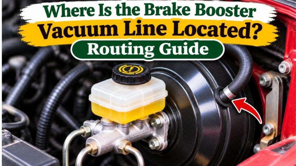
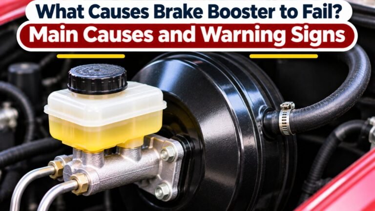
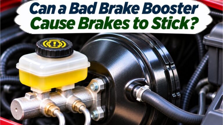
On most conventional left-hand-drive cars sold in the United States, begin at the rear of the engine compartment on the driver’s side. Find the brake fluid reservoir, which is normally mounted on the master cylinder. Behind that master cylinder is the brake booster, often a large, round, black metal housing attached to the firewall.
Look at the engine-facing surface of the booster. A vacuum hose generally attaches through a plastic elbow or check valve fitted into a rubber seal. From there, it runs toward the engine’s intake manifold or the vehicle’s vacuum supply equipment. The hose may angle downward immediately and become difficult to see from above.
NAPA’s brake booster overview identifies the booster between the firewall and master cylinder and describes the vacuum hose attached to its round housing. That provides a useful starting landmark even if your vehicle routes the other end differently.
Important: The metal brake lines attached to the master cylinder are not the booster vacuum line. They carry hydraulic brake fluid. The vacuum hose carries air under reduced pressure and connects to the booster housing rather than the master cylinder’s hydraulic ports.
What Does the Brake Booster Vacuum Hose Look Like?
The Hose and Its Booster-Side Connection
The vacuum supply line is usually larger and more rigid than many small engine-control hoses because it must resist collapsing under vacuum. Depending on the vehicle, it may have a smooth rubber exterior, corrugated protective covering, or molded plastic sections. Its diameter, shape, and routing are vehicle-specific, so do not identify it by size alone.
At the booster, look for a short plastic fitting, sometimes bent at a right angle. The fitting enters a rubber grommet in the booster shell. A hose clamp, molded connector, or quick-release coupling may secure the line to that fitting. Some designs hide the valve inside the hose assembly.
The One-Way Check Valve
The brake booster check valve helps preserve stored vacuum when the engine vacuum supply falls or the engine stops. It may appear as the plastic elbow inserted into the booster or as a separate piece farther along the vacuum hose. Some assemblies have an arrow or an engine-side marking to indicate the correct installation direction.
The AutoZone brake booster check valve guide explains that the valve can be mounted at the booster or within its vacuum supply hose. Therefore, not seeing an obvious separate valve does not necessarily mean one is missing.
How to Locate the Brake Booster Vacuum Line Step by Step
These inspection steps are for a parked vehicle and do not require opening the braking system. Work with the engine off and cool. Follow model-specific precautions if the vehicle has a powered brake accumulator or an electronically controlled brake system.
Step 01: Park Safely and Open the Hood
Park on level ground, set the parking brake, switch off the engine, and keep the vehicle from rolling. Let the engine and exhaust components cool before reaching into the compartment. Use a flashlight instead of leaning against hot or moving equipment. You generally do not need to remove a wheel, raise the vehicle, or loosen a brake fitting simply to identify this hose.
Step 02: Find the Brake Fluid Reservoir and Master Cylinder
Look near the back wall of the engine compartment for a small brake fluid reservoir, often translucent with a labeled cap. It normally sits above or directly on the master cylinder. The master cylinder is a metal hydraulic component with one or more narrow, rigid brake pipes leaving it.
Follow the master cylinder rearward toward the firewall. The larger round or oval housing behind it is usually the vacuum brake booster. On right-hand-drive vehicles or vehicles with unusual packaging, the whole assembly may be on the opposite side or mounted differently.
Step 03: Identify the Vacuum Fitting on the Booster
Look around the front, upper, or side area of the round booster housing for a plastic elbow, straight fitting, or molded hose connection. The precise angle depends on available space. A short vacuum check valve may sit directly in a rubber grommet at this location.
You should be able to distinguish this connection from the hydraulic brake pipes: the hose is not attached to the reservoir or to a threaded brake line port. If you cannot see the fitting, inspect from another safe angle instead of pulling on the tubing.
Step 04: Trace the Hose Toward the Engine
Follow the hose with your eyes and flashlight, noting where it passes behind the intake manifold, under clips, or near the firewall. Some vehicles use a rubber hose for the entire run. Others have a rigid molded section connected to flexible ends. The path may curve around the engine rather than taking a straight route.
Use the existing clips as clues; they keep the line clear of heat, sharp metal, and moving parts. Do not mistake a line passing near the intake manifold for a connection to it. Confirm the actual attachment point if it is visible.
Step 05: Locate the Intake Manifold or Vacuum Pump Connection
On many gasoline engines, the far end attaches to a dedicated manifold-vacuum fitting, sometimes behind or beneath the intake assembly. On vehicles equipped with a vacuum pump, it instead connects to the pump or to associated tubing and a vacuum reservoir. The pump may be engine-driven or electric.
If the connection is buried, consult the correct vacuum routing diagram for the vehicle’s year, engine, and brake system. Avoid removing manifold components just to determine the hose location. Such disassembly can involve gaskets, wiring, or other service requirements.
Step 06: Confirm the Route Against the Vehicle Diagram
Compare the route with the factory service information or a matching under-hood hose diagram. Confirm the check valve, clamps, and any pump or reservoir. Take a photo before planning repairs. If the plumbing has been modified or conflicts with the diagram, have a technician verify it rather than moving hoses between fittings.
Where Does the Brake Booster Vacuum Line Connect to the Engine?
Intake Manifold Vacuum on Many Gasoline Engines
On a conventional naturally aspirated gasoline engine, the intake manifold commonly provides the vacuum used by the booster. The hose attaches to a designated fitting that communicates with manifold vacuum. This is not the same as a small ported-vacuum fitting used for certain engine controls.
The Nissan S13 factory service manual’s vacuum piping section shows the connection between the intake manifold and brake booster, along with the check valve and hose inspection points. Its diagram is specific to that vehicle, but it illustrates why both ends and the valve direction need to be confirmed.
On turbocharged or supercharged engines, intake pressure can vary significantly. The manufacturer may use check valves, a vacuum reservoir, or an auxiliary pump to maintain reliable brake assist. Do not assume a hose attached near the throttle body supplies suitable vacuum without confirming its function.
Vacuum Pumps and Non-Manifold Supply Routes
Some diesel engines produce little usable intake-manifold vacuum for this purpose and use a separate pump. Other engines have a pump to maintain assistance under operating conditions where manifold vacuum is insufficient. An electric pump may operate even when the engine is stopped, depending on its controls.
In those systems, follow the hose from the booster toward the specified pump or reservoir, rather than insisting it must terminate at the intake manifold. The presence of a pump does not change the line’s job: it still supplies the vacuum required for the booster to assist braking.
Why the Vacuum Line Location Varies Between Vehicles
| Vehicle or Brake System | Where to Look | Main Difference |
| Typical left-hand-drive gasoline car | Brake booster behind master cylinder, toward the driver’s side firewall | Hose often runs to intake manifold |
| Right-hand-drive vehicle | Booster near the opposite side of the firewall | Hose may cross more of the engine bay |
| Diesel or vacuum-pump-equipped vehicle | Booster and designated vacuum pump or reservoir | Manifold may not be the vacuum source |
| Turbocharged gasoline vehicle | Booster, check valves, and specified pump or manifold route | Additional vacuum control parts may be present |
| Hydraulic or electronic brake-assist system | Consult the exact brake system diagram | May have no conventional booster vacuum line |
Do not assume that every brake booster uses vacuum. Hydro-Boost systems use hydraulic pressure, commonly from a power steering system, while some modern vehicles use electrically assisted or integrated braking assemblies. A vehicle without a conventional vacuum hose is not necessarily missing a part.
Signs the Brake Booster Vacuum Line Is Damaged
Cracks, Loose Ends, and Collapsed Sections
Examine visible hose sections for splits near bends, hard or brittle rubber, swollen areas, loose clamps, and broken plastic connectors. A line that has softened or collapsed may restrict airflow without showing an obvious open crack. Look for rubbing marks where the hose crosses a bracket or metal edge.
Inspect the grommet and fitting as well as the tubing. A good hose with a leaking end connection can still reduce the available vacuum. Replacement parts must match the intended brake-vacuum application and the vehicle’s connector layout.
Hissing, Hard Pedal, or Rough Idle
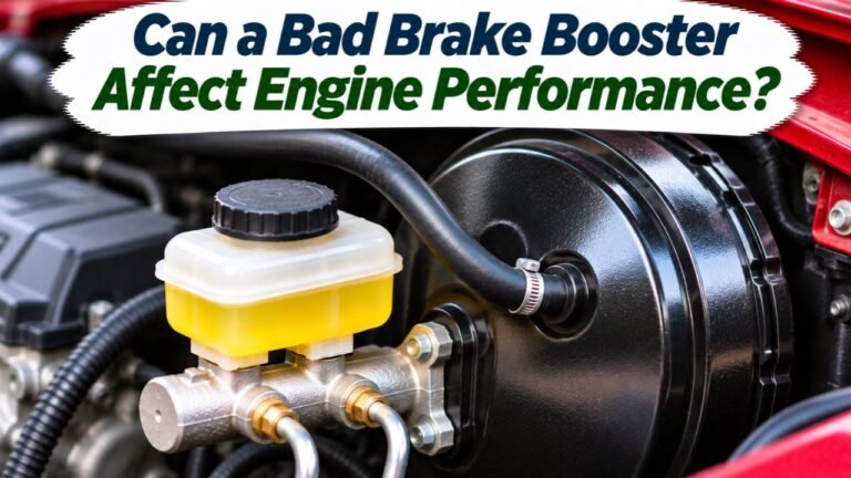
A significant leak can cause a persistent hiss and reduced power assistance, leaving the pedal unusually hard to press. On an engine that relies on intake vacuum, an opening in the hose may also contribute to rough idle because it allows unwanted air into the intake path.
These symptoms are not proof that the hose itself is bad. The check valve, booster diaphragm, vacuum pump, and other brake or engine faults can produce overlapping complaints. Inspect the accessible line first, then use the manufacturer’s test procedure to identify the actual cause.
Can You Check the Vacuum Line Without Removing It?
Yes. A visual inspection is often the best first check. With the engine off and cool, inspect the entire accessible hose, its clips, clamps, check valve, and grommet. Look for disconnected ends, cracking, rubbing, or contact with exhaust components.
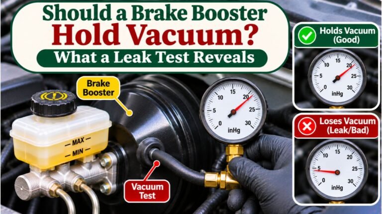
On a conventional vacuum-assisted vehicle, a basic booster response check may offer another clue: with the engine off, press the brake pedal several times to use up stored vacuum, hold firm pressure, and start the engine. The pedal normally moves slightly as assistance builds. If it does not, the cause could be the vacuum supply, check valve, or booster itself.
This check is not suitable for every powered brake design and does not locate a leak precisely. A technician can use approved vacuum measurements and the factory diagnostic steps to isolate the fault. If the pedal is abnormally hard, braking is weak, or a brake warning appears, do not drive until the system has been checked.
What to Know Before Replacing the Brake Booster Vacuum Hose
A replacement hose must tolerate vacuum without collapsing and must withstand its installed heat and routing conditions. Use an original-equipment or correctly specified equivalent assembly. Generic soft tubing, a loose connector, or an incorrect check valve can create another leak.
Observe any molded direction marking on the check valve and follow the manufacturer’s instructions. A valve installed backward can prevent the booster from receiving proper vacuum. Refit all clips and shields so the line cannot rub on belts, pulleys, or hot exhaust parts.
Replacing an external vacuum hose generally does not open the hydraulic brake lines, so it does not by itself require bleeding brake fluid. However, verify the engine connection, vacuum retention, and normal pedal assistance before using the vehicle. If the cause remains uncertain, arrange professional diagnosis.
FAQs About Where Is the Brake Booster Vacuum Line Located
Is the Brake Booster Vacuum Line on the Driver’s Side?
Usually on left-hand-drive vehicles with a conventional booster, but not universally. Start at the brake master cylinder and follow the booster housing rather than relying only on which side of the engine bay you are facing.
Does the Brake Booster Hose Connect to the Intake Manifold?
Often, yes, on conventional gasoline engines. Vehicles with a dedicated vacuum pump may connect the booster to that pump or a related vacuum reservoir instead.
Is the Check Valve Part of the Vacuum Hose?
Sometimes. It may plug directly into the booster, sit in the hose, or be molded into a complete hose assembly. Check the parts diagram for your vehicle before buying a replacement.
Can a Disconnected Vacuum Line Make the Brake Pedal Hard?
Yes. Without adequate vacuum, a conventional booster cannot provide its normal assistance, so stopping may require much more pedal force. Do not drive with a suspected loss of brake assist.
Is There a Brake Booster Vacuum Line on Every Car?
No. Some vehicles use hydraulic assist or electronically controlled braking rather than a conventional vacuum booster. Their service diagrams identify the correct assist system and connections.
Find the Correct Booster Vacuum Hose Before Making Repairs
If you’re asking where is the brake booster vacuum line located, the dependable starting point is the brake booster itself: find the master cylinder near the firewall, look for the vacuum fitting on the larger housing behind it, and follow the line toward its specified vacuum source. Do not assume the connection is identical across engines or model years.
A careful visual trace can reveal a cracked hose, loose check valve, or damaged connector without opening the brake hydraulic system. Confirm the route against the exact vehicle diagram, use the correct replacement parts, and have any brake-assist fault resolved before driving.