Where Does Brake Booster Vacuum Line Connect To? Port Locations
On most gasoline vehicles, the brake booster vacuum line connects the booster check valve to a dedicated vacuum fitting on the engine’s intake manifold. On vehicles that use a separate vacuum pump, the hose instead connects to that pump or to the manufacturer’s vacuum supply assembly. The exact fitting and hose route depend on the engine.
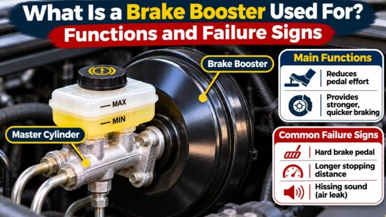
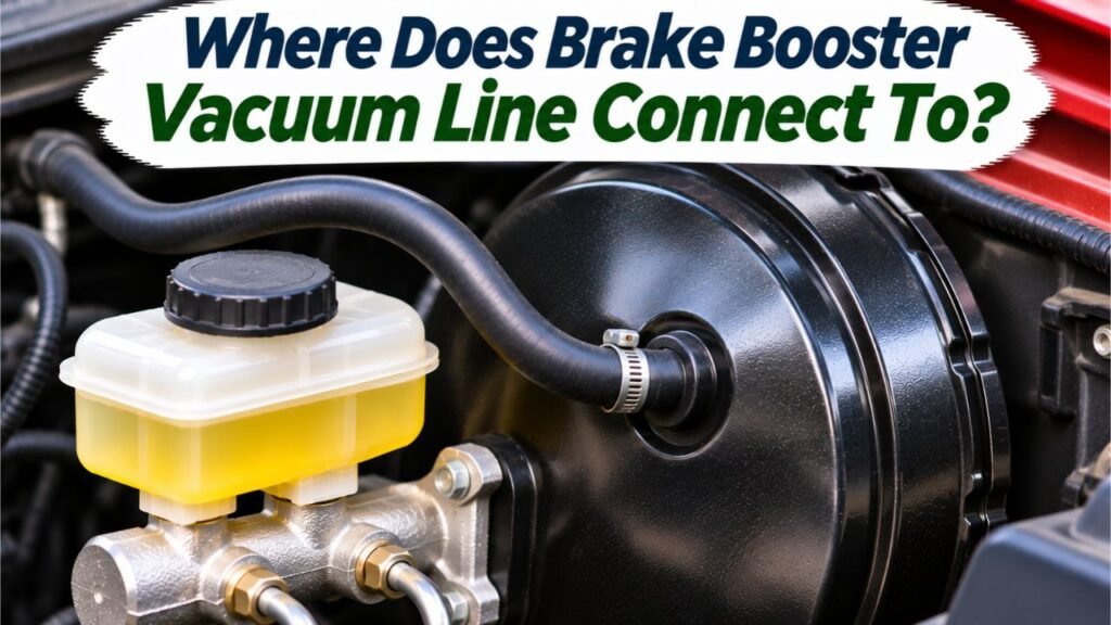
The booster is usually mounted to the firewall behind the brake master cylinder. A comparatively large hose or molded plastic tube carries vacuum from the engine-side source to a one-way valve at the booster. Its job is to provide brake assistance, not carry brake fluid.
A disconnected hose can leave the pedal unexpectedly hard. Connecting it to a convenient-looking fitting is also risky: some nearby ports do not supply suitable manifold vacuum, and others serve emissions or engine-control components.
This guide identifies both ends of the line, shows how to trace the factory routing, explains manifold and vacuum-pump differences, and covers check-valve direction, reconnection, and basic safety checks. It also explains which brake-assist systems do not use a conventional vacuum hose.
Where Does Brake Booster Vacuum Line Connect To on Most Cars?
A conventional vacuum-assisted brake system has two principal connection points: the brake booster check valve at one end and an engine vacuum source at the other. On many naturally aspirated gasoline engines, that source is a full-manifold-vacuum fitting on the intake manifold, downstream of the throttle plate.
The 2003 Chrysler 300M factory service description describes a hose running from the intake manifold to the booster check valve. It also notes that hose routing differs with engine configuration.
The connection is not necessarily on the most visible side of the manifold. It may sit near the rear of the engine, under a cover, beside a wiring harness, or on a molded plastic vacuum distribution fitting. Some engines include a vacuum reservoir, sensor, aspirator, or auxiliary pump in the circuit.
Do not identify the proper port by hose diameter alone. Use the vehicle’s vacuum routing diagram, factory parts illustration, or service manual to confirm the exact connection.
Identify the Two Ends of the Brake Booster Vacuum Hose
The Booster End Near the Firewall
Look behind the brake fluid reservoir and master cylinder. The booster is generally a wide, round housing attached to the firewall. A hose normally enters its front face or upper side through an elbow, a one-way valve, or a combined fitting secured by a rubber grommet.
That fitting is not a brake-fluid connection. The metal brake lines emerge from the master cylinder; the vacuum line enters the booster housing itself. On some designs, the check valve is built into the hose, so it might not be visible at the booster connection.
The Engine End at the Vacuum Source
Follow the same hose toward the engine. On an intake-manifold system, it terminates at a purpose-built nipple, barb, or quick-connect fitting.
On pump-assisted engines, follow the line toward a mechanical or electric vacuum pump instead. Do not confuse a nearby evaporative-emissions purge hose, crankcase ventilation hose, or fuel line with the booster vacuum supply.
How to Trace the Brake Booster Vacuum Line Step by Step
These steps help identify a disconnected hose or verify routing after engine repairs. They are not a substitute for model-specific instructions if fittings must be removed or replaced.
Step 01: Park Safely and Switch Off the Engine
Park on level ground, select Park or Neutral as appropriate, and apply the parking brake. Switch the engine off, remove the key where applicable, and allow hot engine components to cool. Keep hands away from belts, fans, and moving pulleys.
If the brake pedal is already hard or the vehicle is difficult to stop, do not drive it while searching for the line. A vacuum booster without assistance may require much greater foot pressure, even though the hydraulic brakes remain connected.
Step 02: Find the Brake Booster Behind the Master Cylinder
Open the hood and locate the brake-fluid reservoir. The master cylinder beneath it is usually bolted to the booster, which sits against the firewall. Follow the master cylinder rearward rather than searching randomly among the engine’s smaller vacuum lines.
Some engine bays have covers or cramped access. Use a flashlight and the service illustration before removing trim or electrical components. If the vehicle has a hydraulic or integrated electric brake-assist unit, stop and identify that system first.
Step 03: Locate the Hose and One-Way Check Valve
Look for the relatively large hose or rigid molded line entering the booster. It may attach to a plastic elbow seated in a rubber grommet. Examine it without pulling on the fitting; aged plastic can crack or break when twisted.
Look for molded arrows, part numbers, an inline valve, or an electrical vacuum sensor. Note where any support clips are attached. Taking a reference photo before disturbing the assembly can help preserve the original routing.
Step 04: Follow the Line Toward the Intake Manifold or Pump
Trace the hose by sight and gentle hand inspection while the engine is off. Follow every bend, clip, and junction rather than assuming the nearest fitting is its destination. A molded assembly may cross the engine or divide into branches serving a pump and manifold.
If the hose disappears under a cover, consult the correct engine diagram. Do not pull it through a tight gap, disconnect unrelated hoses, or bypass a factory tee or valve to make the route shorter.
Step 05: Confirm the Correct Vacuum Source
For a manifold-fed system, identify the specified port on the intake manifold side of the throttle plate. That is different from an opening on the air-filter tube or a throttle-body port that provides vacuum only under certain throttle conditions.
For a pump-fed design, locate the manufacturer’s vacuum pump and its suction connection. Confirm the path against the service information before attaching anything.
Step 06: Inspect the Hose, Retainers, and Seals
Check the entire visible route for splits, oil-softened rubber, loose clamps, damaged quick-connect tabs, or flattened sections. Inspect the rubber grommet where the valve enters the booster and look for a broken manifold nipple.
Replace damaged pieces with the proper brake-booster vacuum components. Ordinary coolant hose or an unidentified piece of tubing may collapse under vacuum, soften from heat, or fail to seal. Do not apply sealant or tape as a substitute for a broken connector.
Step 07: Reconnect and Check Brake Assistance
Reconnect only after the line path, fitting, and valve orientation have been verified. Seat each connection as specified, engage factory clips, and secure the hose away from hot exhaust parts and moving equipment. Do not force a plastic nipple or reuse a connector that no longer locks.
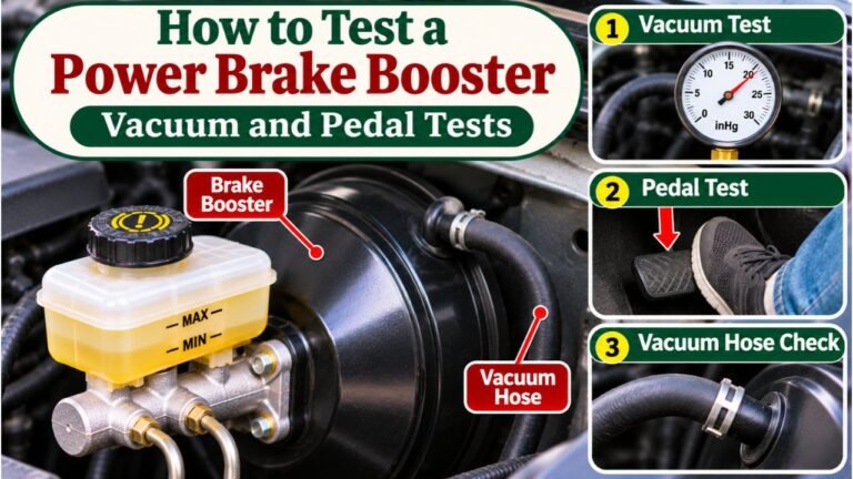
With everything connected, perform the stationary brake-assist test specified for the vehicle. On many conventional vacuum systems, deplete stored assistance with the engine off, hold steady pressure on the pedal, and start the engine. A slight pedal drop indicates that assistance is developing. If the pedal remains abnormally hard, the system requires diagnosis before driving.
Which Intake Manifold Port Should the Booster Use?
The correct connection is usually a dedicated, unrestricted manifold-vacuum port specified by the vehicle manufacturer. It must supply the booster under the operating conditions for which the system was designed.
A manifold port located downstream of the throttle plate typically provides vacuum when a conventional gasoline engine idles. A ported-vacuum fitting near the throttle plate can behave differently and may not provide the correct supply at idle. An inlet pipe upstream of the throttle is also not equivalent to the intake manifold.
Do not move the booster line to a PCV valve connection, EVAP purge fitting, transmission-control line, or an unused-looking nipple just because the hose fits. Altering those circuits can cause vacuum leaks, emissions faults, or inadequate brake assistance.
Factory tees, check valves, reservoirs, and aspirators must remain in the specified circuit. If routing is missing, consult an engine-specific diagram.
When the Brake Booster Vacuum Line Connects to a Pump
Diesel engines generally do not provide the same dependable intake-manifold vacuum as a throttled gasoline engine. Many therefore use a mechanical vacuum pump or another dedicated source. Turbocharged gasoline engines, hybrids, and certain efficient engines may also use supplemental vacuum assistance.
HELLA’s overview of automotive vacuum pumps explains that electric pumps can maintain brake-booster assistance when intake vacuum is insufficient, including under some operating conditions and engine designs.
A mechanical pump may be driven by the engine; an electric pump may be mounted elsewhere in the engine compartment. The hose can run through additional valves and sensors before reaching the booster. Some vehicles combine manifold vacuum with a pump, so both sources can be involved.
Where the Brake Booster Check Valve Goes and Which Way It Faces
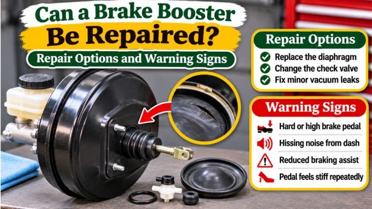
The one-way check valve allows the vacuum source to evacuate air from the booster while helping prevent stored vacuum from escaping when engine vacuum falls. It can be attached directly to the booster or installed in the hose assembly.
Direction matters. For example, the 2008 Saturn Astra check-valve and hose service instructions specify that the arrow on that vehicle’s non-return valve points toward the intake manifold or vacuum pump. That is a verified example, not a substitute for checking another model’s markings.
An incorrectly fitted valve can block evacuation of the booster or prevent adequate vacuum retention. Never guess based on how the plastic elbow looks. If the valve is built into a molded hose assembly, install the correct replacement in its specified orientation.
Symptoms of a Disconnected or Leaking Booster Vacuum Line
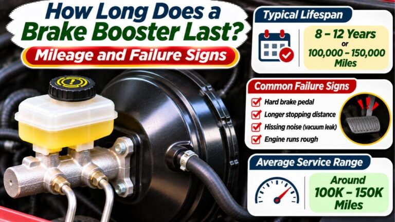
A disconnected or cracked hose can remove some or all vacuum assistance. The most noticeable symptom is often a hard brake pedal that requires unusually high pressure. Depending on the engine, a large manifold vacuum leak can also cause rough idle, hissing, hesitation, or a warning light.
| Symptom | What It May Suggest |
| Brake pedal becomes very hard | Loss of vacuum assistance |
| Hissing near the booster or manifold | Leaking hose, seal, or fitting |
| Engine runs roughly at idle | Possible intake vacuum leak |
| Brake assist fades after shutdown | Check valve or stored-vacuum leak |
| Pedal feels soft or sinks | Possible hydraulic problem, not just the hose |
Do not diagnose the booster as defective based on a hard pedal alone. The hose, source, check valve, and booster can all affect assistance. A disconnected line should be treated as a safety problem until the correct connection and braking operation are confirmed.
How to Check Whether the Vacuum Connection Is Working
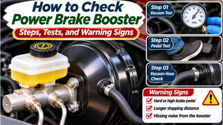
Begin with a visual inspection for an unplugged port, loose fitting, cracked grommet, or collapsed hose. With the engine off, make sure the hose is routed correctly and all connections are secure.
A failed engine-start pedal test points to the vacuum-assist system but does not identify the faulty component.
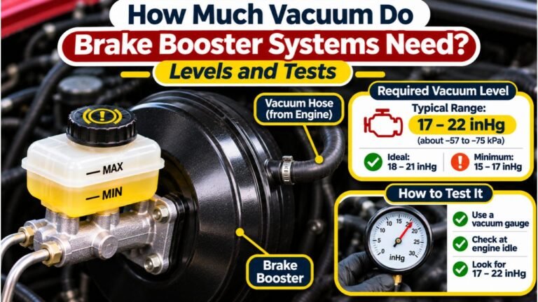
A technician can compare vacuum at the supply source and at the booster using suitable gauges and the vehicle’s test procedure. Low vacuum at the source points toward the engine or pump; adequate source vacuum but poor assistance points toward the hose, check valve, or booster. Never disconnect a hose near moving engine components or leave an open manifold port while operating the engine.
Can You Replace the Hose Without Bleeding the Brakes?
Usually, yes. Replacing only the external vacuum hose or check valve does not open the hydraulic brake lines, so it does not normally introduce air into the brake fluid. However, the correct connection and booster operation still must be verified.
Follow the manufacturer’s removal procedure. Some valves pull from a grommet after residual vacuum is depleted; other hoses have quick-connect clips, permanent valve assemblies, or one-time-use clamps. Replace damaged seals and retainers as required, rather than using a universal hose assembly without checking fit.
If the master cylinder or hydraulic brake lines were disconnected for another repair, bleeding requirements are separate and must be followed. Never assume vacuum-line repair resolves a soft or sinking pedal caused by hydraulic faults.
Does Every Power Brake Booster Have a Vacuum Line?
No. A hydraulic Hydro-Boost system uses pressurized hydraulic fluid, often supplied by a power-steering pump, rather than a traditional intake-manifold vacuum hose. Many newer vehicles use electronically controlled brake assistance and may not have a recognizable round vacuum booster.
Some electric and hybrid vehicles still use a conventional vacuum booster supplied by an electric vacuum pump. The presence of an electric motor therefore does not, by itself, tell you which assist system is installed. Identify the hardware and consult the vehicle documentation before attempting hose work.
FAQs About Where Does Brake Booster Vacuum Line Connect To
Does the Brake Booster Hose Connect to the Throttle Body?
Generally, it connects to a specified manifold vacuum source, not an arbitrary throttle-body fitting. Certain engines have integrated fittings near the throttle body, so the exact location must be confirmed from the factory routing information.
Can the Brake Booster Vacuum Hose Connect to Any Open Intake Port?
No. The port must provide the correct vacuum supply and be intended for the brake-assist system. Other openings may have different vacuum characteristics or serve emissions and engine controls.
Is the Brake Booster Vacuum Hose Connected to the Master Cylinder?
No. The vacuum line attaches to the booster housing or its check valve. The master cylinder bolts to the booster and connects to hydraulic brake lines instead.
What Happens if You Drive With the Vacuum Hose Disconnected?
The brake pedal can become much harder, and stopping can require considerably more force. An open manifold port may also disrupt engine idle. Do not drive until the correct line is restored and braking is verified.
Can a Bad Check Valve Feel Like a Disconnected Vacuum Hose?
Yes. A leaking or incorrectly oriented check valve can reduce stored vacuum assistance. Inspect the valve and supply connections before concluding that the booster itself has failed.
Connect the Booster Vacuum Line to the Right Source
If you’re asking where does brake booster vacuum line connect to, the normal answer is the intake manifold’s designated vacuum port on many gasoline engines, or the specified vacuum pump circuit on pump-assisted vehicles. At the other end, the line attaches to the brake booster through a one-way valve or integrated fitting.
The practical goal is to restore the original, sealed route rather than choose a fitting that merely matches the hose. Confirm the source, check-valve orientation, hose condition, and factory connections before completing a stationary brake-assist check.
A hard pedal, persistent hiss, or uncertain hose routing warrants professional diagnosis. Brake assistance must be dependable before the vehicle returns to the road.