Where Does the Brake Booster Hose Connect To? Routing Explained
On most gasoline vehicles with vacuum-assisted brakes, the brake booster hose connects the booster’s one-way check valve to a dedicated vacuum fitting on the engine’s intake manifold. Vehicles that use a separate vacuum pump route the hose to that pump, sometimes through additional valves and connections. The correct destination depends on the brake assist system, not simply which engine fitting is nearby.
The booster is typically mounted against the firewall behind the brake master cylinder. Its hose carries vacuum, not brake fluid. If that hose has come loose, cracked, or been replaced incorrectly, the brake pedal may become unusually hard and the engine may develop a vacuum leak.
The connection can be difficult to spot because the line may run behind the engine, under a cover, or through molded plastic tubing. Some systems also have a check valve, vacuum sensor, or branch leading to a supplemental pump.
This guide explains where each end connects, how to trace the hose under the hood, how routing differs by engine type, and how to recognize a connection that needs repair.
Where Does the Brake Booster Hose Connect To on Most Cars?
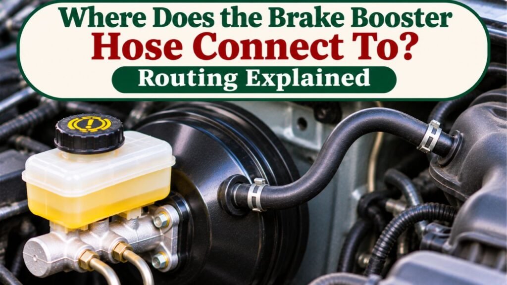
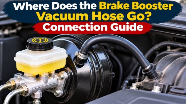
A typical vacuum brake booster has two ends to its vacuum supply path. One end connects at the booster housing, usually through a plastic check valve seated in a rubber grommet. The other end connects to a suitable vacuum source: most often a port on the engine intake manifold, downstream of the throttle plate.
The manifold supplies vacuum that the booster uses to assist the master cylinder. This is separate from the brake-fluid circuit.
CARDONE’s vacuum brake booster diagnostic guide identifies the intake manifold as a common engine-side vacuum source and explains how cracked or collapsed supply hoses can reduce braking assistance. This is why the correct hose, routing, and airtight connections matter as much as the booster itself.
The Brake Booster End of the Hose
Look for the large round booster housing immediately behind the master cylinder. A fairly large vacuum line enters its front-facing shell, often through a right-angle plastic fitting. On many vehicles, that fitting is the one-way check valve, pressed into a rubber sealing grommet.
On other vehicles, the check valve sits partway along the hose or is molded into the hose assembly. A sensor or additional connector may also be present. The hose should attach to the designated booster fitting, not to the master cylinder’s brake-fluid reservoir or its metal hydraulic lines.
The Engine End of the Hose
On a conventional gasoline engine, follow the line toward a relatively large nipple or dedicated connector on the intake manifold. The port may be on the side, top, or rear of the manifold. Some manufacturers use a rigid plastic pipe for part of the route and a short flexible hose at the connection.
The correct port receives manifold vacuum, not air from the unpressurized intake tube ahead of the throttle plate. A random empty nipple is not a reliable substitute: it could belong to a different emissions or vacuum control system. Verify its identity using the vehicle’s routing diagram.
How to Trace the Brake Booster Hose Under the Hood
Tracing the hose from the booster is usually easier than searching the intake manifold for a matching opening. Work with the engine off and cool, and use the vehicle’s repair information if the hose disappears beneath other components. Do not disconnect a functioning line merely to identify it.
Step 01: Find the Booster Behind the Master Cylinder
Open the hood and locate the brake-fluid reservoir on the driver’s side of many left-hand-drive vehicles. Follow the reservoir down to the master cylinder, then look behind it toward the firewall. The booster is commonly the large, round metal housing there.
Its position varies. Identify the brake assist system before assuming a vacuum hose is present.
Step 02: Locate the Large Vacuum Fitting
Inspect the accessible face of the booster for a plastic elbow, check valve, or hose connector. The vacuum hose is typically much larger than nearby small vacuum-control lines. It may have a molded bend and a clip or clamp that keeps it clear of other components.
Do not pull on an aged elbow; brittle fittings can break. Use a flashlight to inspect hidden connections.
Step 03: Follow the Hose Toward Its Vacuum Source
Trace the hose visually from the booster, noting every molded elbow, bracket, junction, and valve. It may rise over the intake, loop behind the engine, or disappear briefly under an engine cover. Where rigid tubing and flexible sections meet, check that each joint belongs to the same assembly.
A branch may connect a factory pump, sensor, or valve. Do not disconnect or reverse it.
Step 04: Confirm the Intake Port or Pump Connection
For a manifold-fed system, identify the hose’s endpoint on a dedicated manifold vacuum fitting. For a pump-fed system, follow the line to the suction side of the vacuum pump or its specified distribution assembly. Check for arrows or molded identifiers on valves, but interpret them according to the part’s service instructions.
If the endpoint is hidden, consult a factory diagram for the exact year, engine, and brake system.
Brake Booster Hose Connections on Different Engine Types
The hose’s destination changes when the engine cannot consistently supply enough intake vacuum, or when the vehicle uses a different form of brake assist.
| Brake Assist Arrangement | Typical Hose Destination | Important Detail |
| Conventional gasoline vacuum booster | Intake manifold vacuum port | Usually includes a check valve at or near the booster |
| Vacuum booster with mechanical pump | Engine-driven vacuum pump | Pump location varies by engine |
| Vacuum booster with electric pump | Electric pump or combined manifold-and-pump circuit | May include sensors, branches, and extra valves |
| Hydraulic power brake assist | Hydraulic pressure and return hoses | Not a conventional vacuum booster hose |
Gasoline Engines With Manifold Vacuum
Naturally aspirated gasoline engines commonly supply the booster from the intake manifold. The hose often runs between the rear or side of the intake and the firewall. During acceleration, available manifold vacuum can drop, so the one-way valve helps preserve vacuum already stored in the booster.
Do not tap into an unrelated accessory line; a restricted port can reduce assistance.
Diesel, Turbocharged, and Pump-Assisted Engines
Diesel engines and some turbocharged gasoline engines cannot rely on intake manifold vacuum in the same way. They may use an engine-driven pump or an electric pump. A few systems combine a manifold connection with a supplemental pump, so the hose may pass through multiple valves.
HELLA’s electric vacuum pump technical guide describes how a pump draws air through the booster and connecting vacuum lines, and explains that installation position and control arrangements vary. Pumps may sit low in the engine bay. Confirm the full factory hose route.
Hydraulic and Electronically Controlled Brake Assist
A hydraulic brake booster, sometimes called hydro-boost, uses pressurized hydraulic fluid rather than a large manifold-vacuum hose. Its pressure and return lines must not be confused with vacuum connections. Some hybrid and electric vehicles use integrated electronic brake control and have no traditional vacuum hose to trace.
Check vehicle-specific instructions before touching a system that can build pressure with the engine off.
Where the Brake Booster Check Valve Fits Into the Hose
The check valve normally sits at the booster inlet or somewhere along its vacuum supply line. Its purpose is to let air leave the booster toward the vacuum source while preventing air from rushing back when engine vacuum drops. That stored vacuum supports assisted braking for a limited number of applications after the engine stops.
AutoZone’s brake booster check valve guide describes three common layouts: a valve seated in the booster grommet, a valve installed inline, and a valve integrated into a molded hose assembly. It also notes that a leaking valve or grommet can produce a hard pedal and loss of vacuum reserve.
Why Valve Direction Matters
A check valve is not simply a hollow connector. It must permit airflow in the intended direction: from the booster toward the engine or pump vacuum source. A reversed valve may prevent adequate vacuum from developing inside the booster, leaving the brake pedal hard.
Follow the replacement valve’s markings and vehicle instructions, not elbow shape.
Why the Rubber Grommet Matters
The grommet seals the space between the valve and the booster housing. A split, hardened, or loose grommet can admit outside air even when the hose and valve are undamaged. This can imitate an internal booster leak.
Replace damaged seals with specified parts; do not rely on glue or tape.
What Happens if the Booster Hose Is Loose or Connected Incorrectly?
A disconnected booster hose can produce two problems at once: loss of brake assistance and an air leak at the engine-side vacuum source. The exact symptoms depend on whether the hose fell off at the booster, manifold, pump, or an intermediate joint.
A Hard Brake Pedal and Longer Stopping Distance
Without enough vacuum, the booster cannot provide its normal assistance. The hydraulic brakes may still operate on a conventional system, but the driver must push the pedal much harder. Available braking performance can be seriously affected, especially during an emergency stop.
Do not drive to see whether the brakes improve at higher engine speed. Keep the vehicle parked and arrange a proper inspection if the hose is disconnected, the pedal suddenly feels hard, or braking is uncertain.
Rough Idle, Hissing, or an Engine Warning Light
An open intake manifold fitting allows unmetered air into some gasoline engines. The result may be a rough idle, audible hiss, stalling, or an engine fault code. These symptoms can overlap with a damaged intake gasket, PCV hose, or another vacuum leak.
Hissing near the firewall may indicate a booster or valve leak. Confirm with inspection and appropriate testing.
Connecting to the Wrong Engine Fitting
The booster hose should not be connected to a random fitting on the intake tube, throttle-body ventilation circuit, PCV system, or evaporative-emissions plumbing. A port upstream of the throttle may not provide the required vacuum; an unrelated manifold port may be restricted or controlled for another device.
Master cylinder brake lines carry pressurized fluid, not vacuum.
Inspecting and Reconnecting a Brake Booster Vacuum Hose Safely
A loose hose should be reattached only after confirming the correct endpoint and condition of every fitting. An intact-looking exterior does not guarantee that an old rubber hose has not softened, collapsed internally, or split on its underside.
Check the Hose Material, Shape, and Connections
Look for cracks at bends, oil-soaked rubber, damaged plastic joints, and places where the line rubs against brackets. Check whether the factory hose uses a clamp, locking connector, molded elbow, or integrated valve. If the line is damaged, replace it with a vehicle-approved brake booster vacuum hose assembly or an equivalent part specifically rated for the application.
Do not substitute coolant hose or undersized tubing. Preserve factory supports and clearance from heat and moving parts.
Restore the Correct Connection Without Forcing It
With the engine off and the system made safe under the service instructions, compare the hose to the diagram and check that each sealing surface is clean. Seat the appropriate connector fully and reinstall its specified clamp or locking clip. Never force a hard plastic fitting onto an incorrect port or add an improvised adapter.
Replace cracked valves or grommets. Follow special shutdown procedures on electronically controlled systems.
Verify Brake Assist Before Returning to Service
Once the system is restored, a conventional vacuum booster can be checked while stationary. With the engine off, press the pedal several times to use stored vacuum. Hold moderate pedal pressure, then start the engine. A slight downward pedal movement generally indicates that assistance has returned.
If the pedal stays hard, hissing persists, or warnings appear, do not drive. Have the vacuum system tested.
FAQs About Where Does the Brake Booster Hose Connect To
Does the Brake Booster Hose Connect Directly to the Intake Manifold?
On many conventional gasoline vehicles, yes. It connects to a dedicated manifold vacuum port, with a check valve at or near the booster. Pump-assisted systems can use a different route.
Does the Booster Hose Connect to the Brake Master Cylinder?
No. The master cylinder is mechanically attached to the booster and carries brake fluid through metal hydraulic lines. The large vacuum hose connects to the booster housing or its check valve.
Can the Brake Booster Hose Connect to Any Vacuum Port?
No. The connection must provide the correct vacuum source and match the vehicle’s designed routing. An unrelated port may be restricted, controlled, or unable to supply dependable brake assist.
Where Does the Brake Booster Hose Go on a Diesel Engine?
Many diesel vehicles use an engine-driven or electric vacuum pump. The hose runs from the booster to that pump or its specified vacuum distribution circuit, rather than relying on intake manifold suction.
Can a Disconnected Brake Booster Hose Cause a Hard Pedal?
Yes. A disconnected hose can remove vacuum assistance and greatly increase pedal effort. On a manifold-fed gasoline engine, it may also create a vacuum leak and rough idle. Do not drive until the fault is repaired and braking is verified.
Follow the Correct Vacuum Source Before Driving
For anyone asking where does the brake booster hose connect to, the usual answer is the intake manifold on a conventional gasoline engine, with a one-way check valve at or near the booster. On diesel, turbocharged, or pump-assisted vehicles, the endpoint may instead be a dedicated vacuum pump or a more complex factory vacuum circuit.
Trace the hose from the booster, confirm its destination with the correct service diagram, and inspect the connectors and seals. If the hose has been disconnected or the brake pedal is unusually hard, repair and verify the system before driving rather than guessing at a nearby vacuum fitting.