Where Does the Wear Indicator Go on Brake Pads? Placement Guide
On many floating-caliper vehicles, the pad with the metal wear tab installs on the inboard, piston-side position, but that is not a universal rule. The exact pad, axle, and upper-or-lower orientation are vehicle-specific. Match the replacement set to the service information or pad-maker instructions before installing it.
Putting the indicator on the wrong pad can defeat the warning function. It may contact the rotor too early, fail to touch it at the intended pad thickness, or place the tab where the caliper or rotor rotation does not match the original design.
Correct placement gives the mechanical squealer its intended chance to warn you before the friction material is fully worn away. That can prevent the steel backing plate from grinding against the rotor and turning a routine pad job into a pad-and-rotor repair.
Brake-pad condition is a real inspection issue in the United States. During the Commercial Vehicle Safety Alliance’s 2024 Brake Safety Week, inspectors performed 14,692 commercial-vehicle inspections in the U.S. and found lining or pad violations on 310 power units and 172 towed units. That data covers commercial vehicles, not ordinary passenger cars, but it shows why friction-material condition and brake inspection deserve attention.
For the question where does the wear indicator go on brake pads, the safest general answer is: on many common floating-caliper systems, the squealer is fitted to the inner pad next to the caliper piston. Some vehicles place it on the outer pad, use a different edge, fit indicators on more than one pad, or use an electronic sensor instead.
What stood out to me while checking OE and brake-supplier guidance was the lack of a single placement rule that fits every car. ADVICS specifically notes that mechanical wear-sensor position can differ between inboard and outboard pads by application, while a Toyota service example specifies an inner pad with the indicator facing downward.
The sections below show how to identify the inner and outer pads, how the metal squealer works, why upper-versus-lower placement matters, what to do when both new pads look similar, and how electronic wear sensors differ from simple metal tabs.
Where Does the Wear Indicator Go on Brake Pads?
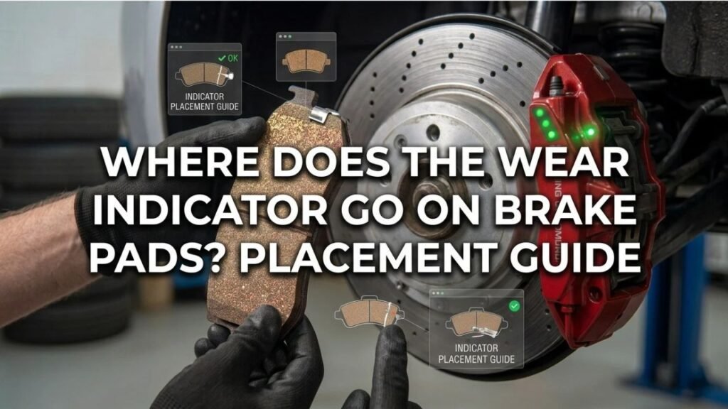
The wear indicator is usually a small metal tab attached to one edge of a brake pad backing plate. As the friction material wears down, the tab reaches the rotor and produces a high-pitched metallic sound.
For many single-piston floating calipers, the indicator pad is the inner or inboard pad, which sits against the caliper piston. Treat that as a common pattern, not a universal installation rule.
Common Position on a Floating Caliper
A floating caliper normally has a piston on the inboard side. When the brake pedal is pressed, the piston pushes the inner pad against the rotor and the caliper body slides so the outer pad also clamps the rotor.
Many manufacturers place the mechanical squealer on the inner pad. That location also makes sense from an inspection standpoint because the inner pad can be harder to see through the wheel and may wear differently if slide pins, the piston, or pad hardware are not moving freely.
Look for these clues when identifying the inner pad:
- A spring or clip designed to fit into the caliper piston
- A backing-plate shape that matches the piston side
- An attached mechanical wear tab
- An electronic sensor slot or lead on applications that monitor the inner pad
- Markings supplied by the pad manufacturer
Do not force a pad into a position based only on the wear tab. Pad ears, shims, piston clips, chamfers, and sensor provisions can make the intended position clear.
Vehicles That Use a Different Position
Some brake systems place the indicator on the outer pad, use indicators on multiple pads, or specify a particular pad on only one side of the axle. Multi-piston fixed calipers can also use layouts that do not follow the common single-piston pattern.
The replacement pad manufacturer’s instructions, factory service information, or a reliable parts diagram should settle the position. If the new pad set differs from the removed set, verify the part number and application rather than assuming the old layout must be copied.
Key Takeaway: The inner, piston-side pad is a common location for a mechanical wear indicator, but the vehicle’s specified pad position and orientation take priority.
Does the Wear Indicator Go on the Top or Bottom?
There is no safe universal rule saying every squealer belongs at the top, bottom, leading edge, or trailing edge.
The correct edge is tied to caliper design, pad shape, rotor direction, and the way the indicator was engineered to contact the disc. On one vehicle the tab may sit low on the inner pad; another design may place it high or on the opposite pad.
This is one reason generic advice such as “always put the squealer on the leading edge” can create problems.
Leading Edge and Trailing Edge Explained
The leading edge is the part of the pad that the rotating rotor reaches first as it moves through the caliper during normal forward travel. The trailing edge is the opposite end.
Those positions change with left-versus-right brake assemblies because the rotors rotate in opposite directions when viewed from the same side of each wheel. A tab position described only as “front” or “rear” can therefore be misleading without a vehicle-specific diagram.
If the service procedure states “indicator down,” “indicator up,” “leading edge,” or another orientation, follow that instruction exactly. Toyota service information for one front brake application, for example, calls for the indicator plate on the inner pad and specifies that the wear indicator face downward. That example should not be copied to unrelated models.
Do Not Mirror the Pads by Guessing
A left-side pad arrangement is not always copied visually onto the right side. Pad sets can contain different inboard and outboard pieces, different chamfers, or more than one wear tab.
Lay out all pads before installation. Compare backing plates, friction shapes, shims, clips, sensor slots, and any stamped markings. Then check the service information if the arrangement is not obvious.
Key Takeaway: Upper, lower, leading, and trailing placement is application-specific, so use the exact service diagram rather than a universal edge rule.
How to Identify the Inner and Outer Brake Pads
The inner pad sits on the piston side of the caliper. The outer pad sits against the outer caliper body on the wheel side of the rotor.
On a standard floating caliper, finding the piston is the easiest way to separate the two positions. The pad directly facing that piston is inboard.
Look for a Piston Retaining Clip
Some inner pads have a spring clip on the back that snaps into the hollow caliper piston. If one pad has this type of clip and the other does not, the clipped pad normally belongs on the piston side.
Do not confuse that clip with the wear indicator. The piston clip is part of pad retention. The wear indicator is a smaller tab positioned near an edge of the friction material so it can eventually reach the rotor.
Look for Different Shim and Backing-Plate Shapes
New pads that look identical from the friction side may have different backing plates. One may have a raised shim, different tabs, a piston-contact feature, or an electronic sensor slot.
Set the new pads beside each other before adding lubricant or installing hardware. Small shape differences are easier to spot on a clean bench.
Compare With the Removed Pads Carefully
The old pads can provide a useful reference if they were installed correctly and the new set is the same design.
Do not treat the old position as proof if the brake job has an unknown service history. Someone may have installed the previous pads incorrectly, or the replacement set may use a revised design.
I would use the old pads as one clue, then confirm the arrangement against the service information or the pad manufacturer’s application notes.
Key Takeaway: Identify the piston side first, then use clips, backing-plate features, sensor provisions, and service information to confirm which pad is inner and which is outer.
What Does the Brake Pad Wear Indicator Actually Do?
A mechanical wear indicator is an audible warning device. The bent metal tab is positioned so it reaches the brake rotor after enough friction material has worn away.
Once contact begins, the metal tab can create a sharp squeal or scraping sound. Honda owner information describes a continuous metallic friction sound during braking as the wear indicator rubbing on the rotor and a sign that the pads need replacement.
The squealer is not the part that stops the car. It is a warning feature attached to the pad assembly.
A brake pad should be inspected before it reaches the backing plate. If the friction material disappears completely, the steel backing plate can grind directly against the rotor, causing deep scoring, heat, noise, and poor braking behavior.
Mechanical Wear Indicator vs Electronic Wear Sensor
Mechanical and electronic systems have the same broad purpose, but they work differently.
| Feature | Mechanical Wear Indicator | Electronic Wear Sensor |
| Warning method | High-pitched metal squeal | Dashboard message or warning light |
| Main component | Small metal tab | Sensor element and wiring |
| Rotor contact | Tab contacts rotor | Sensor may wear through or contact as designed |
| Wiring needed | No | Yes |
| Placement | Vehicle-specific pad and edge | Vehicle-specific sensor pad |
| Replacement | Usually part of pad or clip | Sensor may require separate replacement |
Mechanical Squealer
A mechanical squealer needs no wiring. It uses direct contact with the rotor to produce sound.
The pad set may have one squealer, more than one, or none. The number and location are part of the brake design.
Electronic Sensor
An electronic wear sensor uses a wire and sensor element fitted into or onto a designated pad. On many vehicles, only one or two pads across the vehicle carry electronic sensors rather than every pad.
Do not move an electronic sensor to a pad simply because the slot appears to fit. Route the wire exactly as specified so it does not rub on the wheel, rotor, axle, or suspension.
Some electronic sensors are single-use. Once the sensor has worn through or triggered, replacement may be needed with the new pads.
Key Takeaway: A metal squealer makes noise through rotor contact, while an electronic sensor sends an electrical warning; both must go in the vehicle-specified position.
How to Install Brake Pads With a Wear Indicator
Brake work is safety-related, so use the repair procedure and torque specifications for the exact vehicle. Support the vehicle with rated jack stands on a stable surface and never rely on a hydraulic jack alone.
Before disassembly, inspect the new parts. Confirm the axle, part number, pad count, hardware, sensor arrangement, and any left/right or inner/outer markings.
1. Compare the New and Old Pad Shapes
Place the old pad set beside the new one. Match friction shape, backing-plate ears, chamfers, slots, shims, clips, and wear indicators.
If the sets do not match in a way you can explain from updated hardware or service information, stop and verify the part number.
2. Identify the Inboard and Outboard Positions
Find the caliper piston. The pad that sits against it is the inner pad.
Use any piston clip, pad marking, electronic-sensor slot, or backing-plate feature to confirm the new pad position.
3. Confirm Indicator Orientation
Check the service manual, brake-pad instructions, or an OE parts diagram for the wear-tab edge.
Do not bend the indicator to make a guessed arrangement fit. Its height and shape determine when and how it contacts the rotor.
4. Inspect the Caliper and Hardware
Check slide pins, boots, pad abutment areas, piston condition, rotor surfaces, and hardware before fitting the pads.
Pads should move as intended in the bracket. Rust buildup under abutment clips can squeeze the pad ears and cause binding.
5. Keep Lubricant Off the Friction Surfaces
Use only brake lubricant approved for the contact points specified in the service procedure.
Do not put grease on the rotor face or pad friction material. Contaminated friction surfaces may require cleaning or part replacement based on the type and amount of contamination.
6. Reassemble to Vehicle Specifications
Install the pads, hardware, caliper, and fasteners in the specified order. Torque fasteners to the vehicle manufacturer’s figures.
Before moving the vehicle, pump the brake pedal until it becomes firm. The caliper piston may have been pushed back during service, leaving extra clearance until the pads are reseated against the rotors.
Key Takeaway: Verify the parts, identify the piston-side pad, confirm the indicator edge from service information, inspect moving hardware, and reassemble to the vehicle’s specifications.
What Happens if the Wear Indicator Is Installed Wrong?
The result depends on how the tab is misplaced.
It may touch the rotor earlier than intended and create a false wear warning. In another position it may fail to make contact at the intended point, leaving the driver without the expected squeal.
A wrongly positioned pad can also interfere with caliper hardware if the backing plates are not interchangeable.
Do not assume the brakes are assembled correctly just because the pads fit inside the bracket. Brake pads can appear physically similar while using different shims, clips, ears, or friction geometry.
If a new squeal begins immediately after a pad replacement, inspect the installation before assuming the pads simply need time to settle. Look for a misplaced wear tab, bent dust shield, incorrect hardware, pad binding, rotor contact, or foreign material.
What if the Inner Pad Is More Worn Than the Outer Pad?
A small difference may occur, but a large difference deserves inspection.
On a floating caliper, both pads should participate in each stop. If the inner pad is badly worn while the outer pad remains thick, the piston may not be retracting normally, or the caliper may not be sliding as intended.
If the outer pad is badly worn while the inner remains thick, seized slide hardware or pad binding can also be involved.
Check for:
- Sticking or corroded slide pins
- Torn slide-pin boots
- Pad ears seized in the bracket
- Corrosion beneath abutment clips
- A caliper piston that does not move or retract normally
- A brake hose problem that traps hydraulic pressure
- Rotor or caliper damage
The wear indicator is not a substitute for inspecting both pads. It reports the condition at the location where it is fitted.
Conclusion
For anyone asking where does the wear indicator go on brake pads, the common answer is the inboard, piston-side pad on many floating-caliper vehicles, but exact placement varies by brake design. The top, bottom, leading, or trailing edge should come from the service information for that vehicle.
A mechanical indicator needs to reach the rotor at the intended pad-wear point without interfering with the caliper. Electronic sensors also belong only in their designated pad positions and need correct wire routing.
My recommendation is simple: use the inner-pad rule only as a starting clue. Match the pad set to the piston, backing-plate features, markings, and service diagram before tightening anything. If the pad orientation remains unclear, stop the brake job until the correct layout is confirmed.
FAQs About Brake Pad Wear Indicator Placement
Does the brake pad with the wear indicator go inside or outside?
On many common floating-caliper systems, it goes on the inside pad next to the piston. This is a common arrangement rather than a rule for every vehicle. Some brake systems use an outer-pad indicator, multiple indicators, or an electronic sensor in a different position. Confirm the application before installation.
Should the brake pad wear indicator be on the top or bottom?
It varies by vehicle. Some service procedures specify the indicator at the bottom, while other designs use another edge. Do not choose the position from appearance alone. Check the factory service procedure, pad-maker instructions, or a vehicle-specific brake diagram.
Does the wear indicator face the rotor?
The tab is arranged so that its contact end can reach the rotor once the pad wears to its designed warning point. It should not touch the rotor when a new pad is correctly installed unless the pad design states otherwise. Do not bend the tab simply to make it face a direction that seems right.
Why is the wear indicator usually on only one brake pad?
One indicator can provide an audible warning for the monitored pad position, which keeps the design simple. Many floating-caliper applications monitor an inboard pad. That does not mean the other pads should be ignored; all pads need inspection because sticking hardware can create uneven wear.
Can I move a wear indicator clip to another brake pad?
Only if the pad manufacturer or service procedure calls for a removable indicator to be transferred. Many wear tabs are fixed to the pad backing plate and are not intended to be relocated. If a clip is separate, install it only in the specified position.
What does a brake pad wear indicator sound like?
A mechanical indicator usually produces a high-pitched metallic squeal or scraping sound as the tab contacts the spinning rotor. The sound may appear mainly during braking or become more frequent as the pad wears farther. Grinding accompanied by poor braking should be treated as a more serious warning and inspected promptly.
What if my new brake pads have no wear indicator?
Some vehicles do not use mechanical squealers on every pad set. They may rely on an electronic wear sensor, visual inspection, a different pad design, or another service method. Confirm that the replacement pads are the correct part number rather than adding a generic clip that was not specified for the brake system.